October Blog - Pool Test
This month, we continued to work on the PVC prototype and also began making a final design. We worked on waterproofing to ensure that there are no leaks in the enclosure tube.

There are two ends of the enclosure tube that have to be sealed: the front and back. To make sure that no water ever leaks through, we use O rings coated in high vacuum grease. In our end caps, we have three O-rings. We clean the metal groove that holds the O rings with a Q-Tip. Then we had to clean the O rings with a cloth. Finally, we re-applied the grease to the O rings and put them back into their slots. The grease helps to create a stronger seal preventing water from getting inside the enclosure tube. We tested the enclosure tube by submerging it four feet in the pool. The seal held and prevented water ingress. We will have to reapply the grease every time we open and close the enclosure tube to protect our electronics. Additionally, a white plastic locking chord goes through the top O ring slot. This chord is removable and has a stopper to prevent the end cap from coming off of the enclosure tube. The only way to take the end cap off is by first removing the locking chord.

The electronics are first tested on the benchtop. We use a power supply instead of a 12V battery because the power supply would be able to limit current in the event that something is wired incorrectly. If there was an incorrect connection, then the battery could potentially deliver enough current to damage the electronics.
With this setup, we were able to connect to the Fathom tether interface board in the enclosure tube and thus the rest of the electronics on the tray. We then connected one of the electronic speed controllers (ESC) to one of the thrusters and were successful in controlling the speed of the thruster with the joystick!
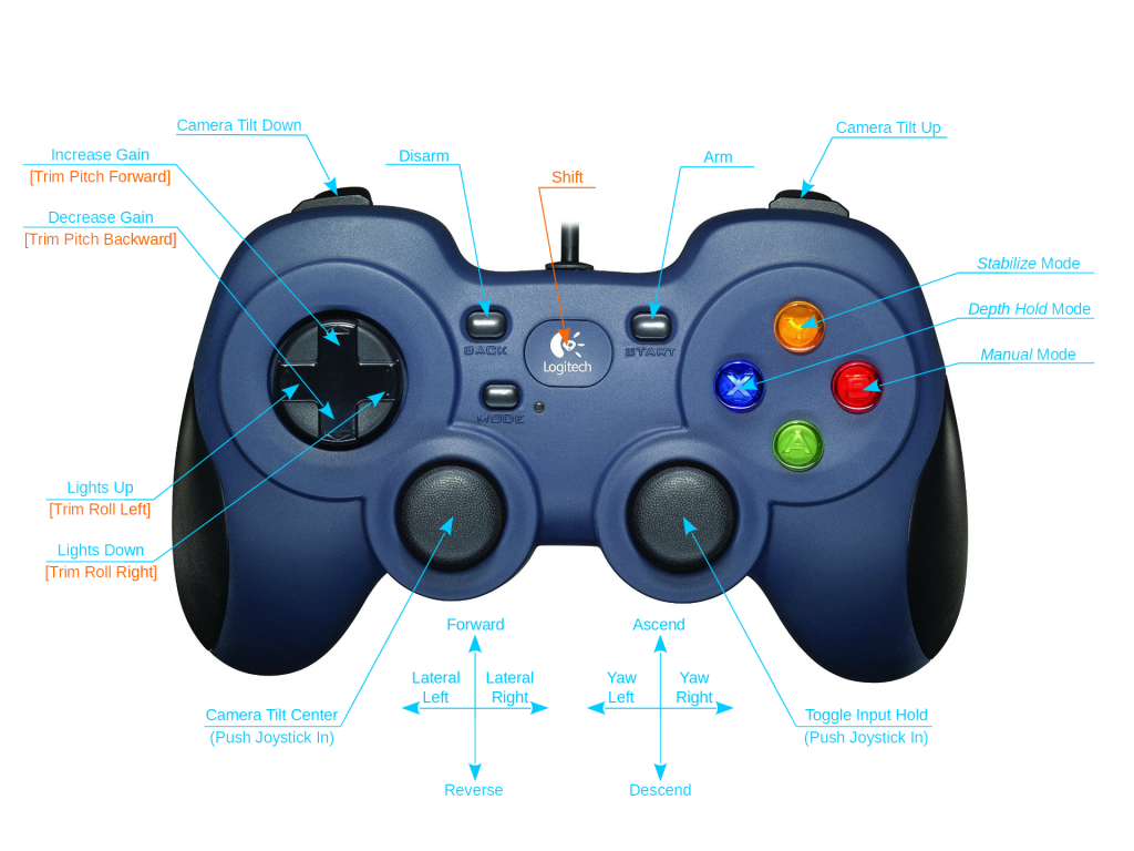
Next we had to make sure the thruster was moving according to the joystick. Since an option to change the motor assignments was not showing up in QGroundControl, we manually changed the wiring of the ESCs to reflect the controls seen in the diagram. First, the ESCs were switched to correspond to the right thrusters. Both vertical thrusters are shown to spin clockwise to ascend and counterclockwise to descend. The horizontal thrusters are shown to spin clockwise to go forwards and counterclockwise to go backwards. The video also shows moving right and left. While doing these tests, it was important to run the thrusters slowly and for short amounts of time because the thrusters are made to operate in water and not in air. If they run too fast for too long, the plastic bushings inside may melt.
We also got the power module telemetry data to show up in the QGroundControl, but it only displayed the voltage and current consumed. We did verify the voltage with a digital multimeter, and the menu seems to be decently close to the actual voltage of the battery. Later we found out there is a way to display the current, just that it’s on the instrument panel.
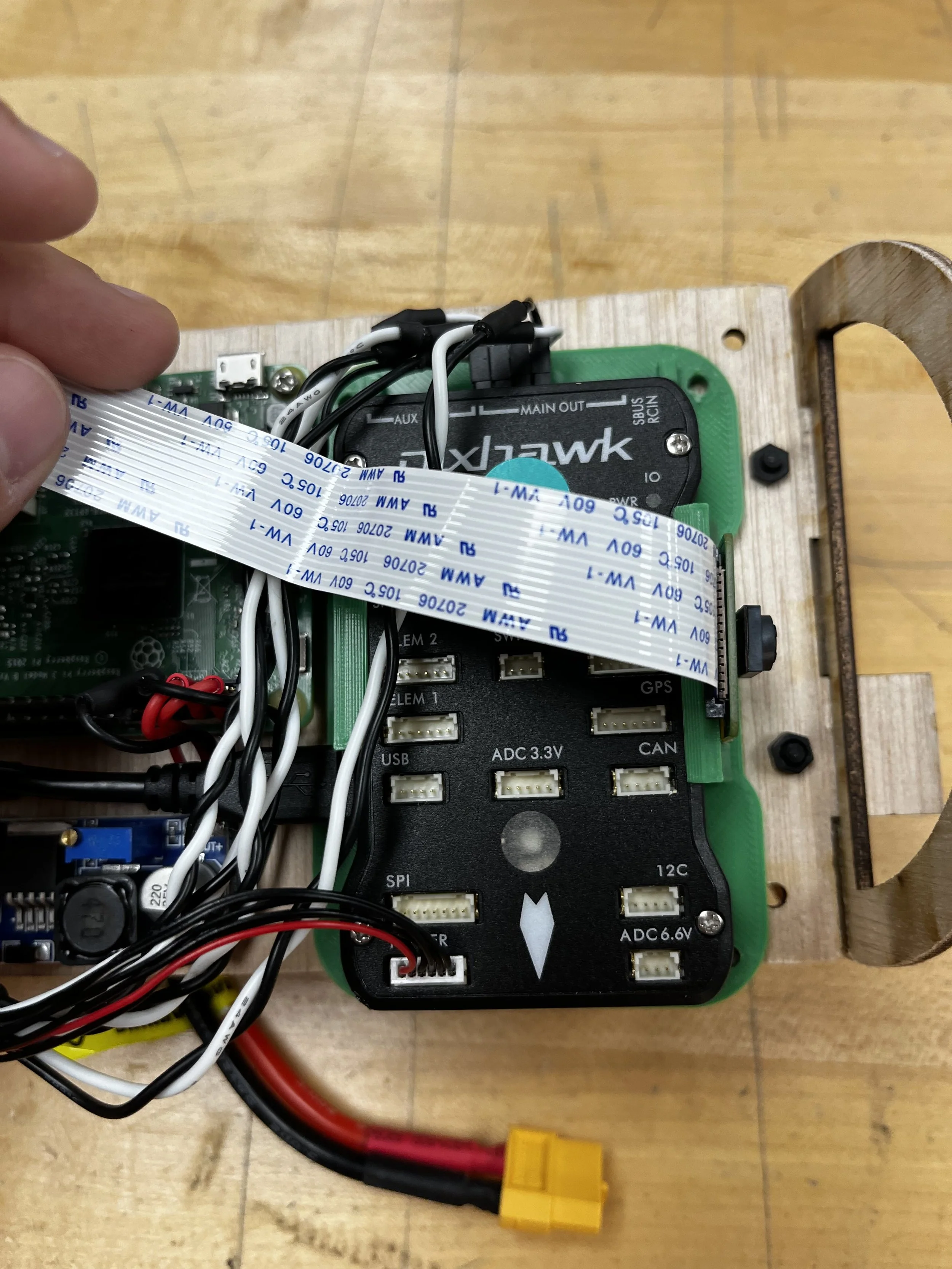
The Raspberry Pi camera successfully connected to the computer through the Fathom interface boards. However because there is not enough room for a proper mount, we modified an existing mount. The Pixhawk is located right next to the dome, and oriented so that the side mounting used to keep the Pixhawk from detaching is facing the dome. We used tape to secure the camera from sliding off of the mount.
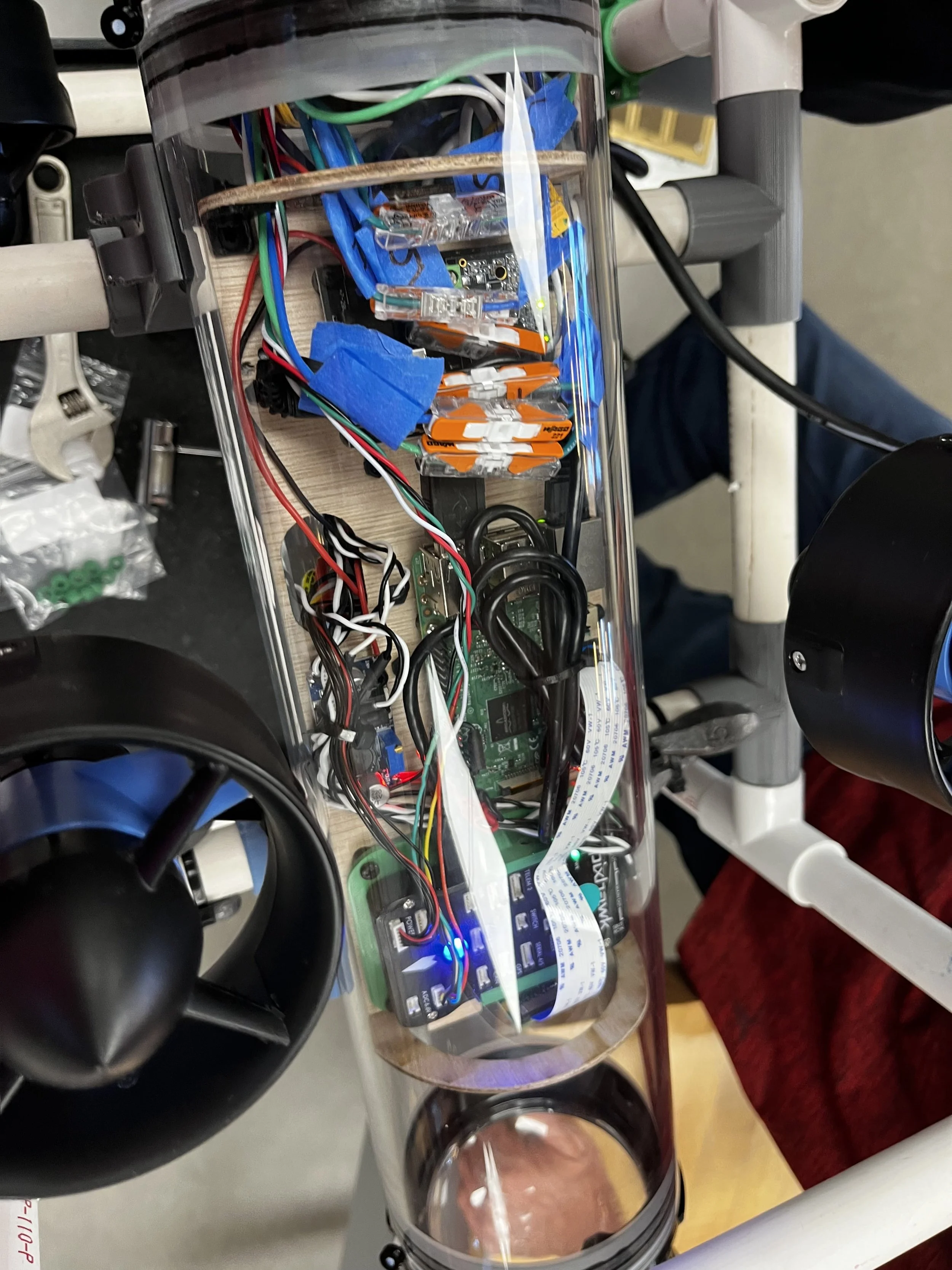
The electronics were then inserted into the enclosure tube. At this point, we decided to use a longer enclosure tube. The small enclosure tube was a really tight fit in length, so it made more sense to use the longer enclosure tube. There are cable penetrators that go through the end cap to reach the electronics that are outside of the enclosure tube. These cable penetrators seal the cable openings. Since the new enclosure tube is much longer, the electronics will have more space to be spread out making cable management easier.
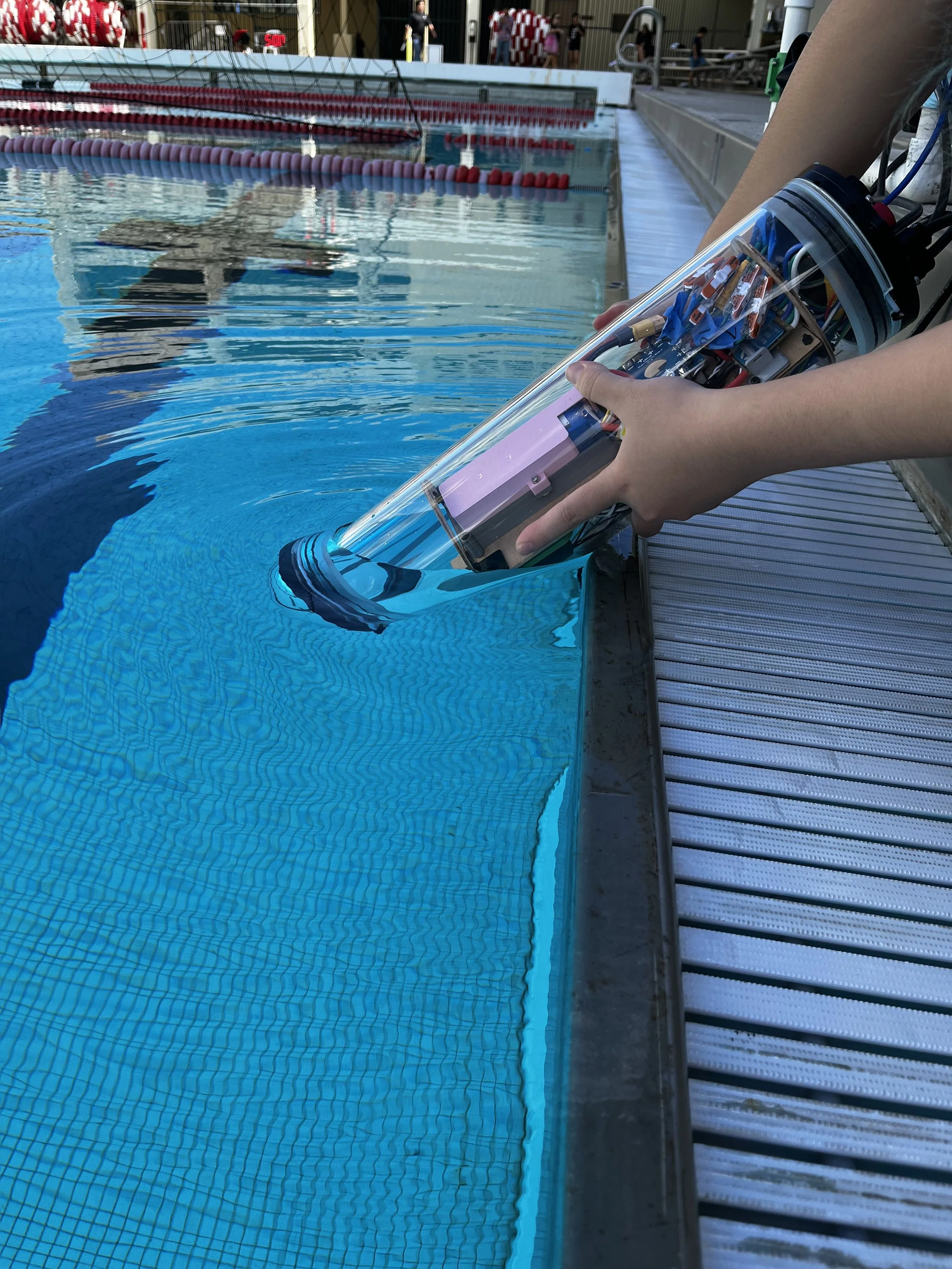
Finally the day of the pool test arrived. We succeeded in getting the PVC prototype done and tested in the pool before the end of our academic school year’s first quarter. After careful waterproofing and sealing the enclosure tube, we first tested just the enclosure tube in the water. We dipped the front end of the enclosure tube, the end without electronics, into the pool and observed that no water got into the enclosure tube.
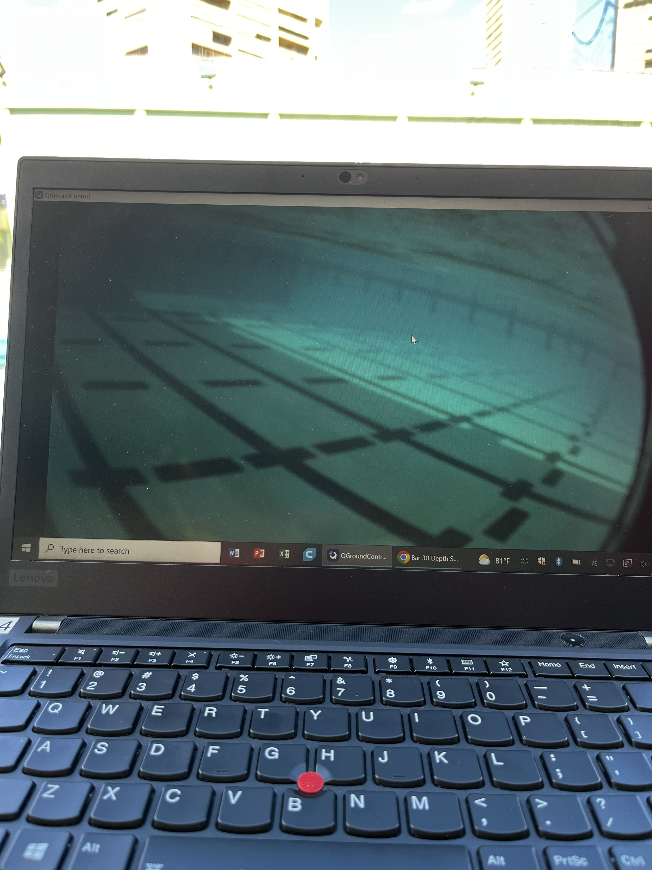
This gave us the green light to proceed with mounting the enclosure tube onto the PVC prototype and putting the whole system into the water. When it was in the water, the ROV sank slowly because it had a slight negative buoyancy. We were able to maintain a connection while the ROV was underwater and move it with all four thrusters controlled by the joystick. The vertical thrusters operated correctly and didn't tilt the ROV because they were centered. On the contrary, the horizontal thrusters tilt the ROV every time they are activated because they are positioned towards the back bottom of the ROV. We also maintained a live video feed.
There is a black rim on the edges of the screen from the dome connecting to the enclosure tube. It should be fixed once a new mount is made. Additionally the feed was quite dark despite the pool being sunny that day because we were in the shade. We will attach lights in the next iteration.