
October Blog - Aluminum ROV
After the PVC ROV pool test, we started to work on a new Aluminum ROV. We were able to test this by the end of the month.
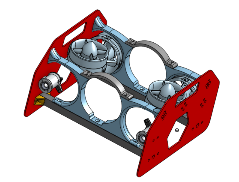
This new version has a more sleek profile, is much smaller, and has lights. The side plates are trapezoidal and the tube mount changed completely. They also feature a hexagonal cut out to increase water flow and a rectangular cutout that serves as a handle to carry the ROV. Instead of using O rings to fasten the tube to the mount, We’re opting to use two 3D printed screw on clamps. In this version, the side plates are connected by both the Bosch bar and tube mount.

The tube sits in the white part which will be attached to the bottom bar and the side plates. The tube fits in pretty well. We created a notch at the bottom of the tube mount to allow the end cap to fit through. The green part on top is the clamp. The tube mount is fastened to the side plate by four screws. Since 3D printed parts do not have threads, we had to put in heated inserts.
We also decided to use Bosch for the middle bars. We cut two pieces to 12.75 inches long using the chop saw. The Bosch pieces come with a 5mm hole but we needed to add threads so we learned how to tap holes into the Bosch. These holes are for a ¼-20 screw.

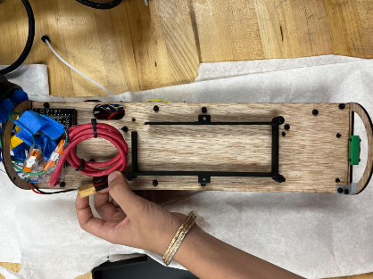
In this iteration, our goal was to incorporate a larger battery and take up a larger amount of the new tube. With this in mind, we kept the battery and Fathom board on one side and the rest of the electronics on the other. With the new length, stability of the tray became a concern because bowing of the wood could occur in the middle. We settled on making the tray thicker at 0.25 inch instead of 0.125.
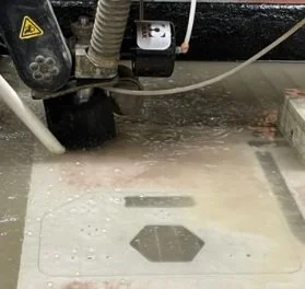
We used the water jet to cut out the side plates. The side plates are .125 inches thick and have all of the mounting holes for the bar, tube mount, thrusters, and lights. After we water jetted the side plates, we sand blasted them to smooth it out. Once the side plates were cut out and smooth. We were able to assemble them. At the same time, our team was working on the new electronics tray.

The old Raspberry Pi camera was secured with tape to the mount. In this iteration, we want something more stable. Since we have a longer tube to work with, the Pixhawk is no longer at the edge of the electronics tray. So instead, this new mount is secured to the front circle of the tray. For this iteration, it is a 3D printed piece. The camera slides in from the top, and is secured by the two screws on the bottom. Additional security is provided from the two flaps on the top. In our first attempt at making this piece, it was too small. In the second iteration we made the gap larger. Even if it doesn’t fit perfectly, we can heat the PLA so that it is more malleable.

For this test, we changed the setup of the electronic tray. To maximize space for the battery, all electronics (except the Fathom tether board) were moved to the top side of the tray while the battery remained on the bottom side.
The signal wires of the thrusters that connect with the ESCs are not yet soldered, so they are connected using WAGO connectors. These ESCs receive power from the power distribution board (PDB), which gets 12V from the power module sitting below the power distribution board (PDB) that is powered by the battery on the opposite side of the tray. The power module also provides 5V to the Pixhawk. The Raspberry Pi also requires 5V, so there is a DC/DC converter that takes the 12V from the PDB and converts it to 5V for the Pi. In the second picture, there is a fathom tether board on the left. This receives 12V from the PDB in one terminal block and in a green terminal block it outputs data to the tether. A wiring diagram is also shown below.


Once everything was configured, it was time to test the ROV in the pool. During the pool test, we first placed the ROV slightly below the surface of the water so it was completely submerged. We then took it out of the pool and checked to make sure that the tube was dry. If it leaked, then we would have had a lot of problems. After checking this, we placed it into the pool so we could drive it around. When we tested it, we noticed that the ROV pitched upwards. The front went up and the back went down. One cause for this is that the ROV is back heavy. The horizontal thrusters and battery on the back of the tube are making the back way heavier than the front. We tried to account for this issue by adding multiple weights to the front of the ROV. While the weights helped a bit, the ROV still pitched upwards. Currently, the ROV is difficult to maneuver.
Other than the pitching, the ROV had a negative buoyancy as it sank to the bottom of the pool. We tried to add blue foam, a low density material, to the back of the ROV but it still sank.

The current wasn’t initially available on the dashboard because we used a power supply for the test bench. Once we connected the battery and input the correct voltage and current capacity, we were able to monitor the battery through the dashboard. This way, we can not only tell if the battery is running low, but also how much current running the motors at full speed takes up.

The pixhawk is able to keep a log of the data recorded during a flight on a micro usb. This can either be downloaded from QGroundControl or manually extracted. However, because QGroundControl can’t read the data, we have to import it to Mission Planner, which can give us both a table and a graph of the data. To see specific data such as current or depth, we can either select from a menu on the side of the screen or use the search bar. Looking at this data we can tell that the maximum current consumed was almost 18A.
We will also look for a way to convert the data into a .cvs (spreadsheet) file so that we can view the data on something more convenient like Google sheets. QGroundControl does seem to have a way to also record in .cvs but the information is less precise. Additionally, Pixhawk begins recording every time we arm the submarine, so we will have to wipe the data before diving to keep track of the logs. This can be done through QGroundControl, but there is no way to do it with a button on the controller (Without modifying the code and adding a custom function).