
September Blog
This month, we wanted to get a PVC prototype designed, fabricated, and running. The focus of our PVC prototype is to get it moving and test how effective our thrusters and the buoyancy of our prototype will be in helping the sub maneuver. In order to accomplish this, we needed to model the prototype, fabricate and assemble, power, and obtain manual control of the sub.
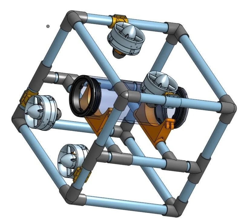
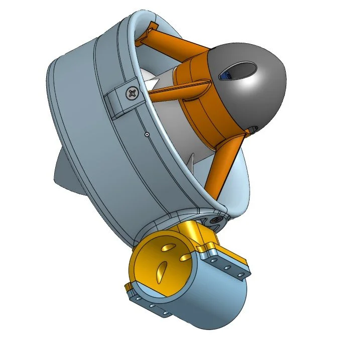
This is the CAD assembly of the complete PVC ROV. The blue pipes are all 324mm (12.75 in) long and form a cube. There are 4 thrusters; 2 horizontal and 2 vertical ones that can be moved anywhere on the frame. The mount is two separate parts that are clamped together with four M3 screws. The thruster is attached to the mount by four mounting holes in the yellow part. The mounting holes are for 6mm long M3 screws. To move them, you need to unclamp it by removing the four screws, and then re-clamp it in the new location. The tube mount can also be moved by adjusting the location of the supporting pipes. The mount consists of a tube that connects to the ROV’s frame and two different ways to attach the tube to the mount. The mount sits in the semi circle and can either be attached by a long zip tie that goes through the small hole or by a rubber band or O-ring that goes around the extended clips on the top. However, the extended clips do not go all the way across the part to create a channel for the zip tie to sit in and there is currently a chance that it snaps due to the tension. In the next iteration we plan to make the clip extension bigger and give it more strength.
The PVC ROV is a 13 inch cube. Since the T-joint has an extrusion in the middle that restricts pipes from going all the way through, the pipes were cut into two parts each 5.875 inches long. Unlike the store-bought T-junctions, the 3D printed ones do not have an interior extrusion that restricts a pipe from passing through so we could slide the T-mount that connects the tube mount along the side pipes. Small holes were drilled into the pipes so that the pipes can fill with water while submerged.
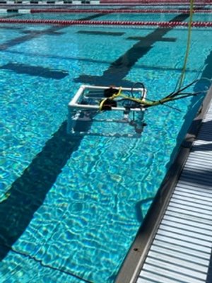
After the ROV was assembled, it was placed in the pool. The ROV maintained upright and didn’t tilt or turn over. When fully submerged underwater or turned upside down, the ROV corrected itself to the upright position. The only problem we encountered was that the ROV tilted upwards and didn’t lie flat because the back was heavier. This weight imbalance was created by the two back thrusters. To fix this, four weights were added to the front of the ROV. This corrected the imbalance and brought the ROV to a level position. Of course, we can play with the weight distribution depending on the type of buoyancy we want and our results will change when the electronics are put in.
After the ROV was assembled, it was placed in the pool. The ROV maintained upright and didn’t tilt or turn over. When fully submerged underwater or turned upside down, the ROV corrected itself to the upright position. The only problem we encountered was that the ROV tilted upwards and didn’t lie flat because the back was heavier. This weight imbalance was created by the two back thrusters. To fix this, four weights were added to the front of the ROV. This corrected the imbalance and brought the ROV to a level position. Of course, we can play with the weight distribution depending on the type of buoyancy we want and our results will change when the electronics are put in.


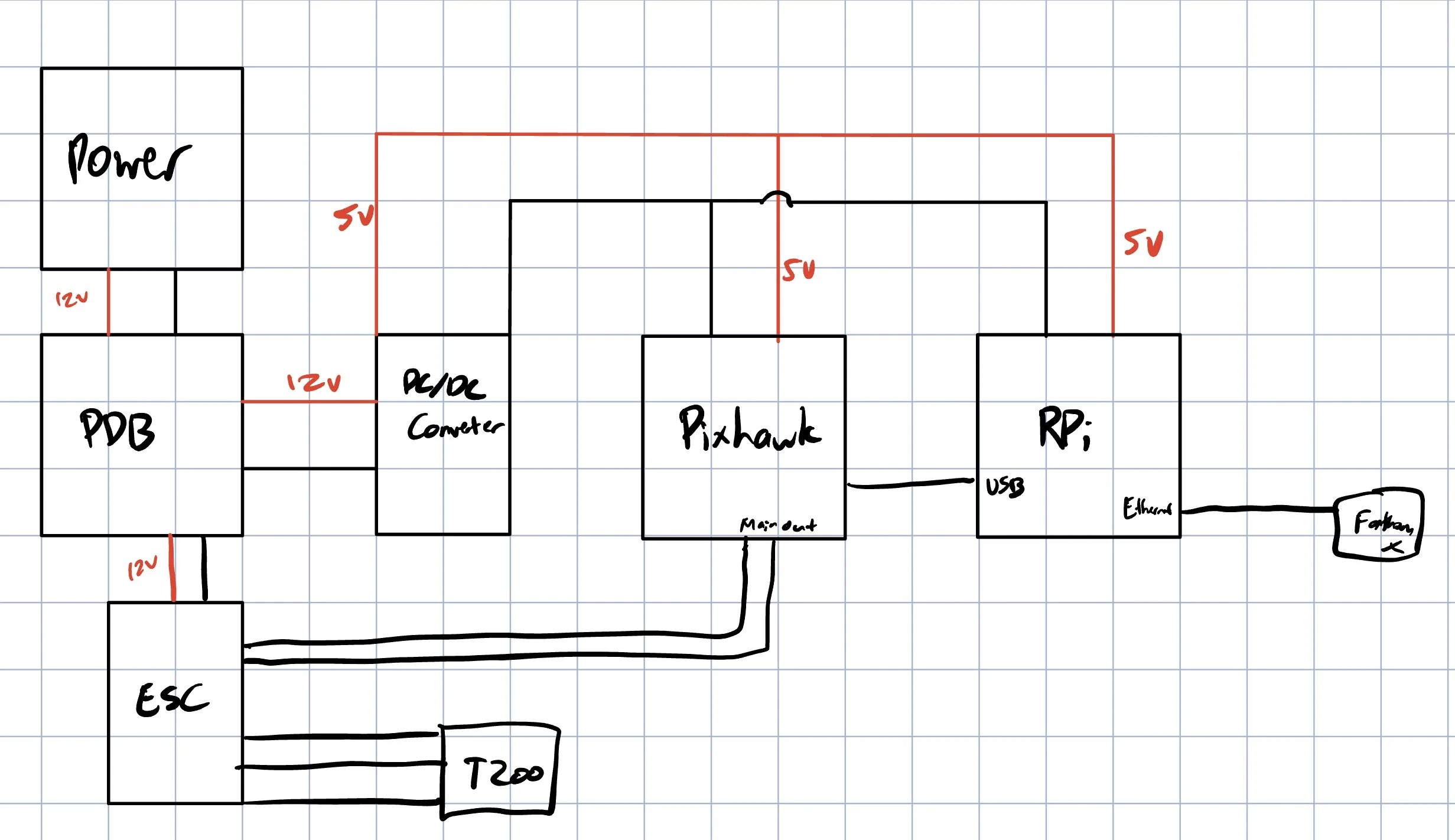
The bulk of the electronics are going to be mounted onto a tray inside the tube. Using the ArduSub’s given connection diagram on the right, we determined that the electronics needed would be thrusters, electronic speed controllers (ESCs), the tether interface board (Fathom X), Pixhawk, and Raspberry Pi 3B. We will be ignoring the camera and lights for now since they are not necessary for this prototype.
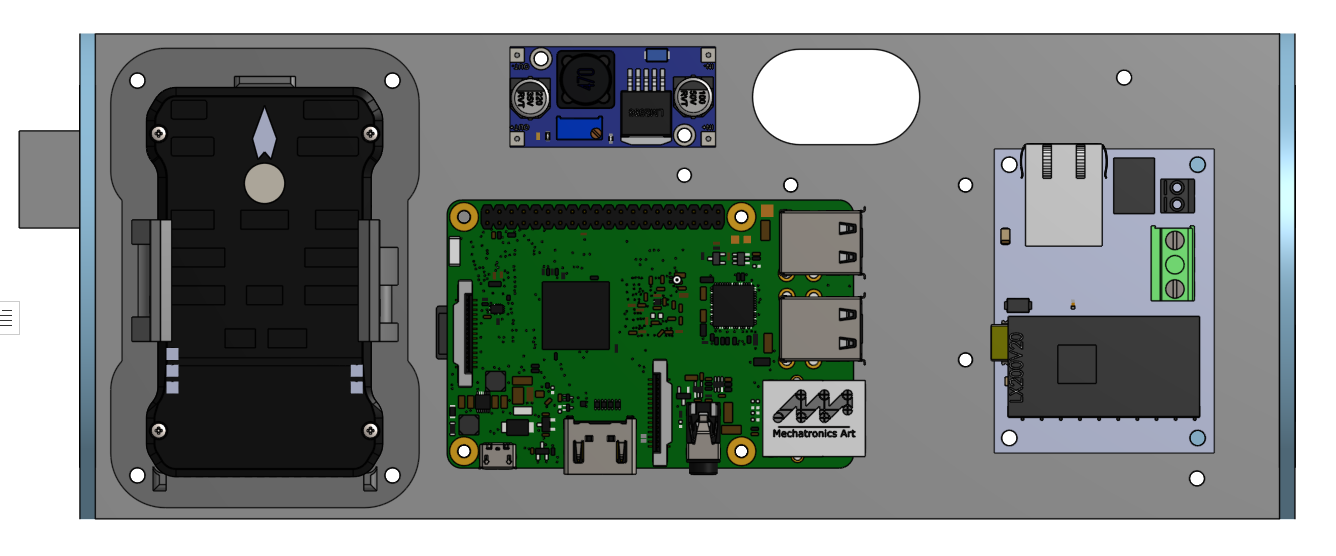
After determining the electronics, power and wiring had to be decided. The Pixhawk and Raspberry Pi will need 5V, but the ESCs and thrusters will need 12V. This means that we will need a 12V battery connected to a power module that goes to a power distribution board (PDB) that distributes the 12V to the ESCs and to a step down DC/DC converter that will take the 12V down to 5V for the Raspberry Pi. The Pixhawk will receive 5V from the power module.

This layout took into account the rigid parts of the cables that would have to connect into the ports (such as the Pi’s USB cables), and the need for room on the edges of the tray. The pi is rotated on the top, and the converter is on top with the pi. Next to the converter is a hole for wires to go from the power distribution board to the converter and the Fathom X. To save space, the ESC mounts are all one piece and makes the wiring to the power distribution board neater. The board is centered and is stacked on top of the power module to save space and allow access to the bottom of the board to power everything.
The Pixhawk is the brain inside of the submarine because it communicates with the computer on the surface and all the other electronics like the sensors and thrusters. An app called QGroundControl is used to both set up and control the Pixhawk through Ardusub. Details on how to set up Ardusub on the Pixhawk can be found here.
After downloading QGroundControl and connecting the Pixhawk to the computer, the software inside the Pixhawk was updated (flashed) with the ArduSub software, the control software we will be using.

A few sensors can be set up without needing to connect the Pixhawk to other hardware. These include the accelerometer, level horizon, and compass. While the compass needs to be calibrated outside for the best results, the other ones can be done indoors. The Pixhawk is tilted to calibrate the accelerometer and level horizon, and pointed north to set up the compass.
Next, the pressure sensor was connected since the chances of it damaging the Pixhawk are low compared to the power connector if something goes wrong. The pressure sensor we are using is one from a previous project. However, the connectors for them were not the correct size and didn’t fit into the Pixhawk’s I2C port (The pressure sensor is set to I2C), so the wires were cut and re-soldered.
First, the pinout of both the I2C port and pressure sensor had to be verified as a match. Power and ground (red and black) wires are the most important when wiring. Since they provide the power for the pressure sensor to work, connecting them backward could damage both the Pixhawk and the pressure sensor. SCL and SDA provide signal and data, which is used for the pressure sensor and Pixhawk to communicate with each other (the pressure sensor tells the Pixhawk what depth the ROV is currently at).
The Raspberry Pi is a companion computer used to record and send a live video feed to the computer above water. To install the software, the 8GB SD card that is inserted into the Pi was flashed. Then, following ArduSub’s instructions, the Ethernet settings from the ground station laptop were changed. It should now be ready for the camera once it comes in after this prototype test.